Creating a new fixture profile
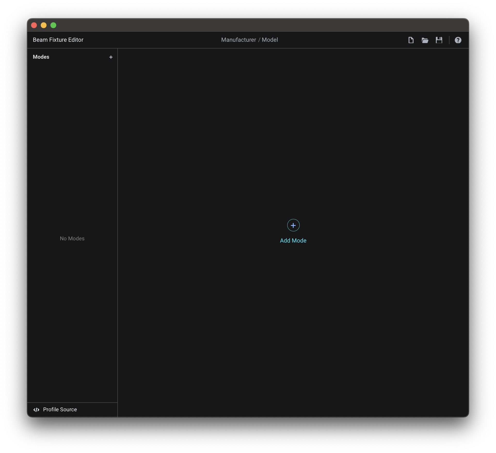
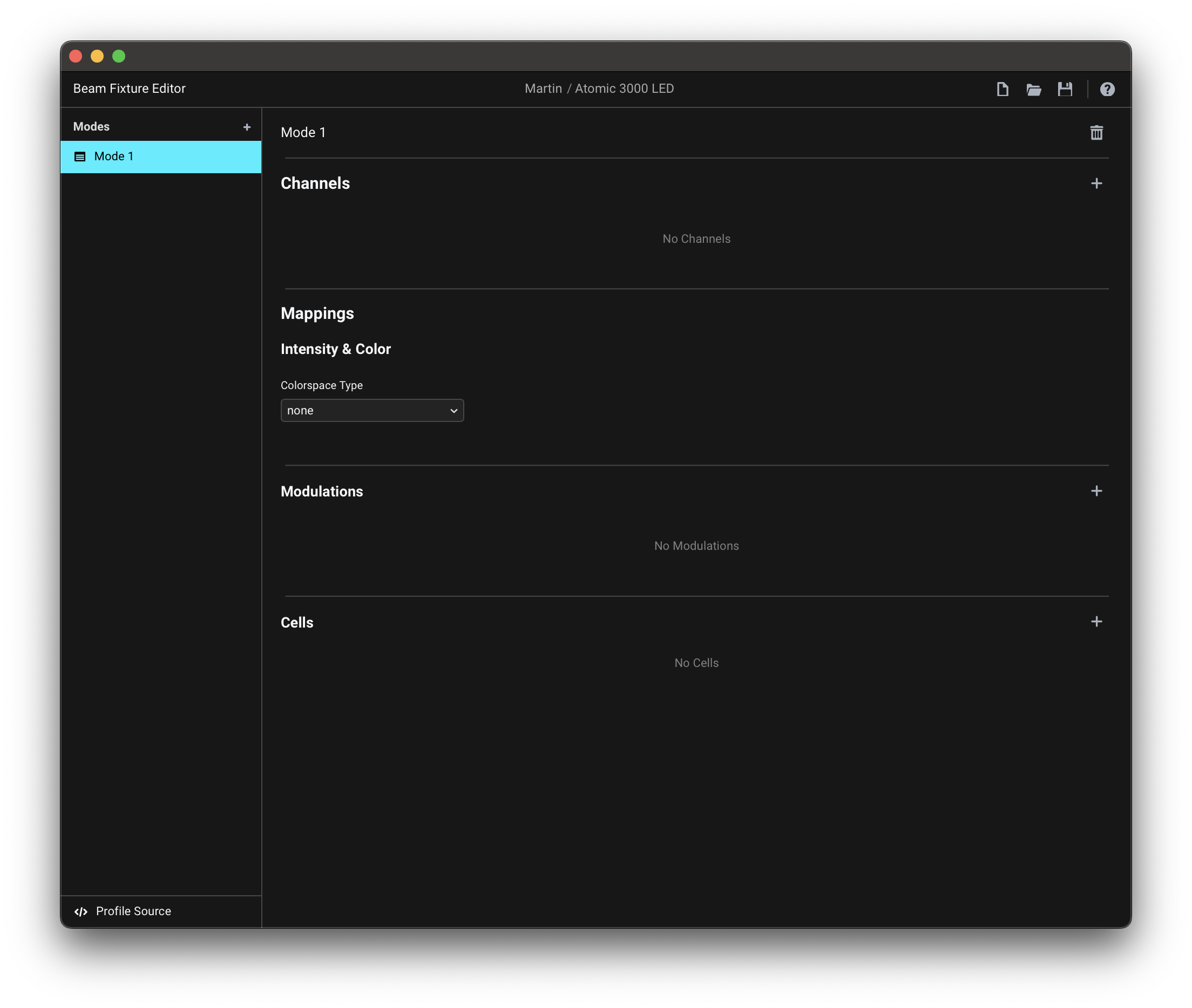
When you open the Fixture Editor you are presented with an empty fixture profile:
To start with a new empty fixture profile at a later point, go to New > Empty fixture profile:
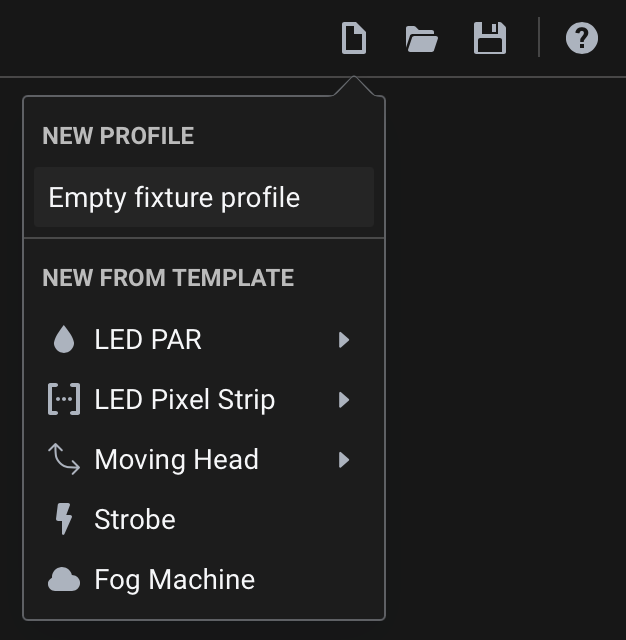
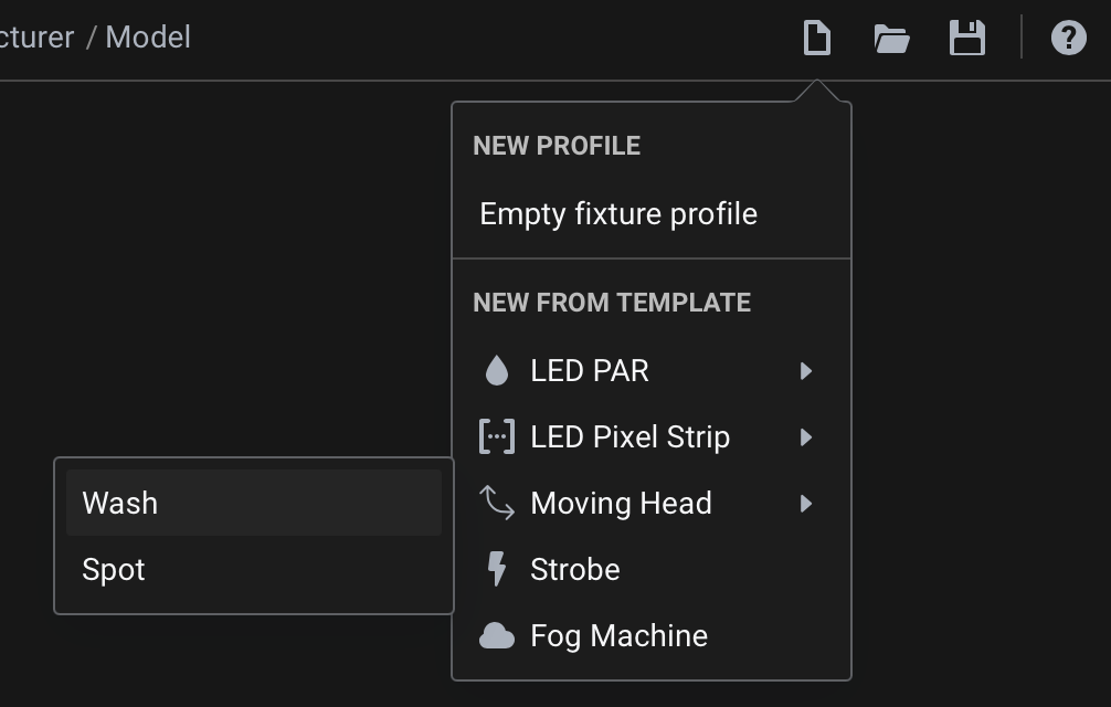
Once you become familiar with the Beam fixture profile structure and various aspects of the Fixture Editor interface, you can also choose to create a new fixture profile from one of the New from Template options as a starting point:
Manufacturer and Model

At the center of the top menu bar are the Manufacturer (1) and Model (2) fields. Fill these in with the corresponding fixture information, e.g. Martin / Atomic 3000 LED.
These fields are used to identify your fixture in Beam's Fixture Patch and should match the manufacturer's official naming when possible.
Modes
Modes determine how a fixture uses DMX channels to control its features. Many lighting fixtures offer multiple DMX operating modes, each with a unique channel layout and functionality, as specified in the fixture's manual. A single fixture profile can contain any number of modes. Once your fixture profile is ready, you can choose from its modes when adding the fixture to the Fixture Patch.
Adding modes
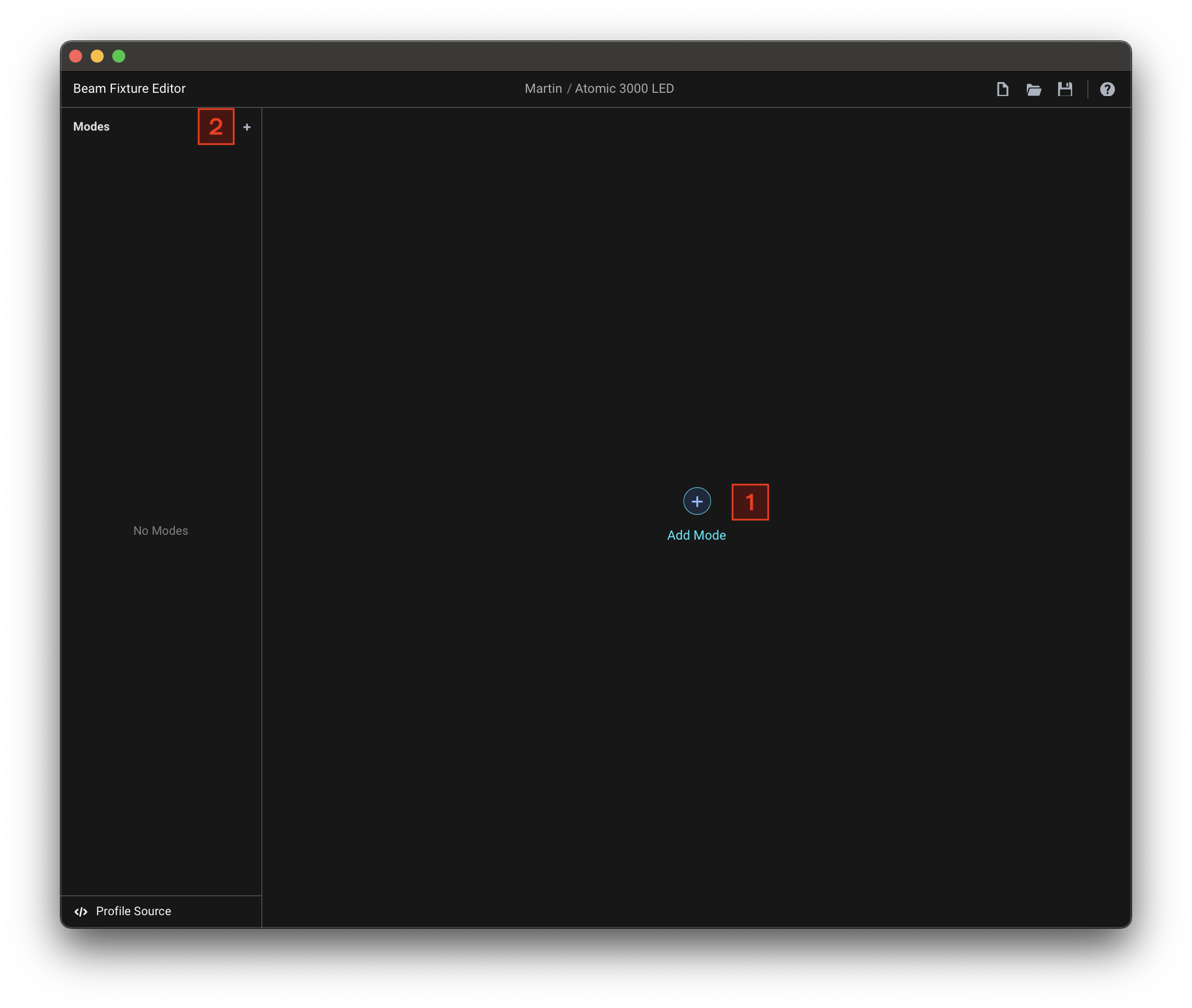
When you start with a new empty fixture profile, you can add the first mode using the Add Mode (1) button in the center of the screen. You can also add modes using the + (2) button in the left-side navigation menu.
After you add a mode, you will see the following view:
Switching between modes
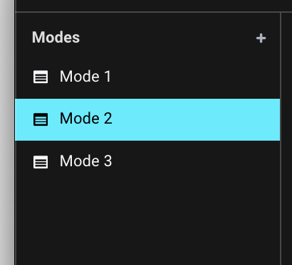
If your fixture profile has more than one mode, you can switch between them through the left-side navigation menu:
Renaming modes
By default modes are assigned names like Mode 1, Mode 2, Mode 3... You can change the mode name at the top of a Mode view:
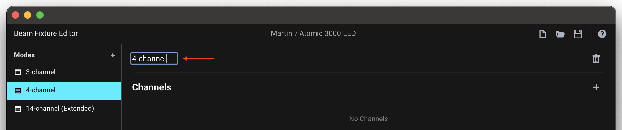
To best distinguish the different modes from each other, we recommend setting this to the mode names as used in the fixture manual, e.g. 3-channel, 4-channel, Basic, Extended...
Deleting modes
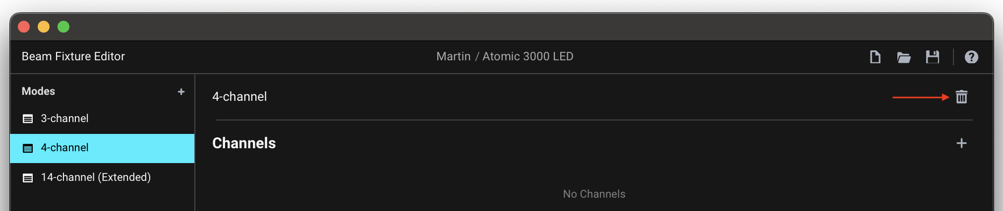
To delete a mode, press the trash-can button at the right of the mode name:
Channels
Channels are DMX control addresses that operate specific fixture functions. The mode's channel layout should match the fixture manual exactly.
Adding channels
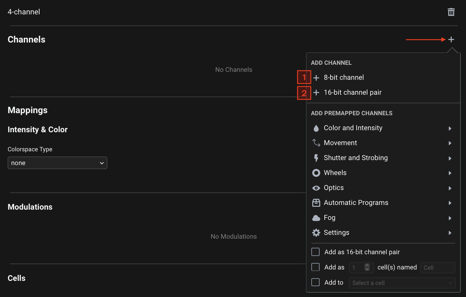
Add a Channel by clicking the + button at the top-right of the Channels section. There are two basic options:
1. 8-bit channel
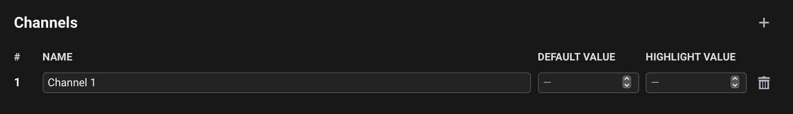
An 8-bit channel is simply a single DMX channel that controls a single fixture function, using DMX values between 0 and 255.
When you add an 8-bit channel, you will see a single channel entry appear in the Channels table:
2. 16-bit channel pair
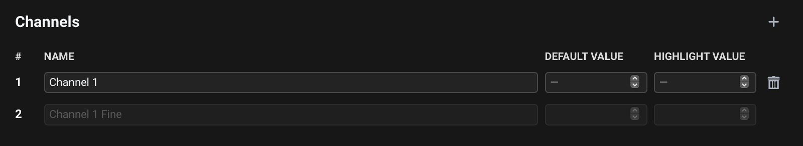
A 16-bit channel pair consists of a pair of coarse (Most Significant Bit / MSB) and fine (Least Significant Bit LSB) DMX channels that together control a single fixture function with a higher precision, using values between 0 and 65535. This allows for finer control resolution, which is commonly used for functions like Pan and Tilt of moving heads, where smooth, precise movements are essential. Beam allows you to control these as a single parameter in a range between 0.0 and 1.0.
When you add a 16-bit channel pair, you will see two channel entries - a coarse channel and a fine channel:
Setting channel properties
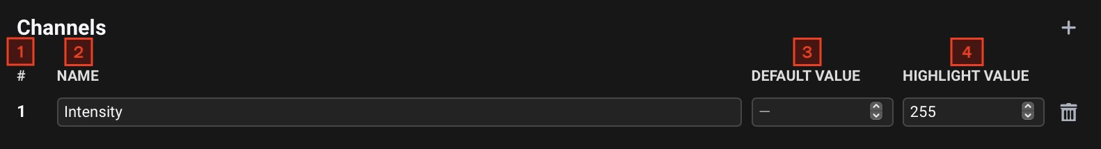
Each channel entry/row has 4 properties:
- # - The channel number. When you have more than one channel, you can change this by dragging the channels to the desired positions.
- Name - A unique, human-readable label for the channel, corresponding to the channel name in the manual. When working with 16-bit channel pairs, only the name of the coarse channel needs to be set - fine channel's name is set automatically.
- Default Value - The value the channel is set to when the fixture is not explicitly controlled by any of the Mappings.
This field is optional - when not specified,
0will be used as the Default Value.
Range:0-255(8-bit single channel) or0-65535(16-bit channel pair, set on the coarse channel). - Highlight Value - The value the channel is set to when enabling Test for the fixture in Beam's Fixture Patch editor.
This field is optional - when not specified, the Default Value will be used as the Highlight Value.
Range:0-255(8-bit single channel) or0-65535(16-bit channel pair, set on the coarse channel).
- Example 1: RGB fixture
- Example 2: Moving head
- Example 3: Moving head with 16-bit control
Here's how you would set up channels for a simple RGB fixture:
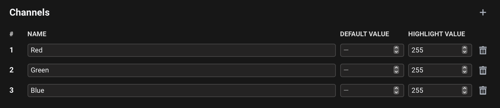
The Highlight Values for Red/Green/Blue channels are set to 255, to ensure the fixture lights up when we press Test with the fixture selected in the Fixture Patch.
Let's say our fixture is a moving head and we also add channels for controlling Pan and Tilt:

The Default Values for Pan and Tilt channels are set to 128, half of the DMX value range (0-255), to ensure the moving head is centered in its default state.
If we are working with a moving head that allows for a finer, 16-bit control of Pan and Tilt, with two channels for each function, we would instead add two 16-bit channel pairs:
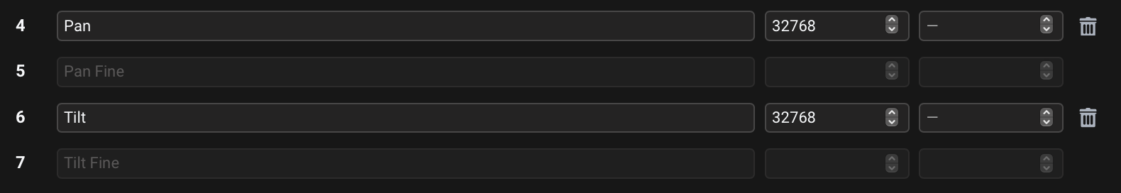
The Default Values for Pan and Tilt channels are now 32768, half of the 16-bit DMX value range (0-65535).
For a more efficient workflow, the Fixture Editor provides presets for a number of common channel types through the Add Premapped Channels section of the menu for adding Channels. This feature, which creates pre-configured Channels with appropriate Mappings in one step, is covered in detail in the next article.
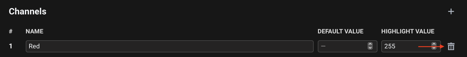
Deleting channels
To delete a channel, press the button at its right:
Mappings
Mappings determine how Beam's lighting controls map to the fixture's Channels. They enable using a consistent set of controls across different fixtures, even when their DMX channel layouts differ, and allow you to reuse your Ableton Live Sets or Max patches with different lighting rigs without needing to reprogram the controls.
Intensity & Color
Intensity & Color mappings define how Beam's lighting controls map to the fixture's Channels related to intensity/dimming and color-mixing.
They enable you to work with intensity and color through a unified set of controls, such as Intensity parameter and color chooser on Beam for Live devices, as well as red, green, blue and dim control parameter keywords in both Beam for Live devices and Beam for Max objects. Beam can automatically convert sets of these parameter values to DMX values for intensity and color-mixing channels of fixtures with different DMX channel layouts.
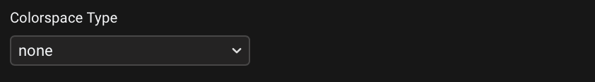
Choose the Colorspace Type corresponding to the available intensity and color-mixing channels on the fixture:
- none
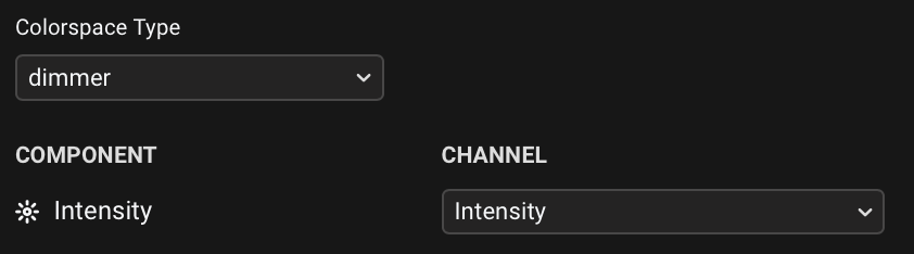
- dimmer
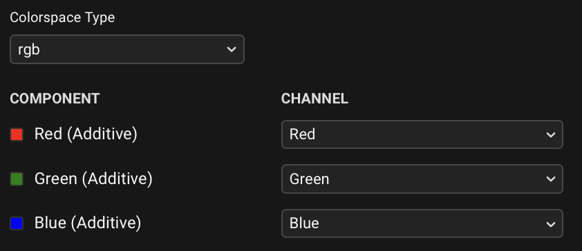
- rgb
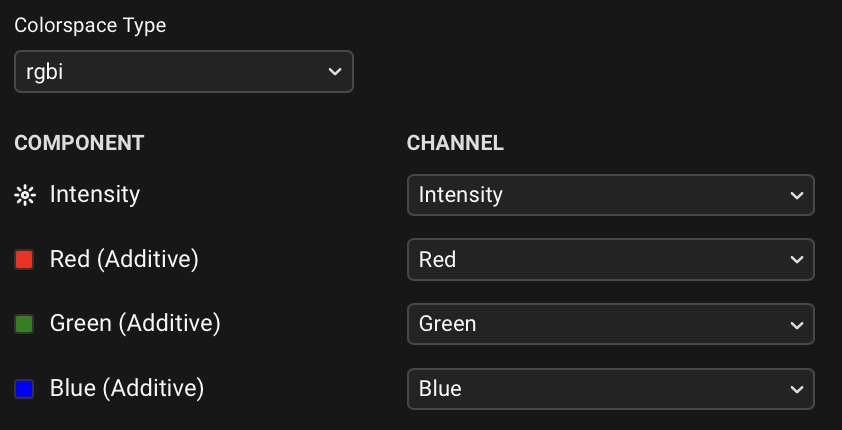
- rgbi
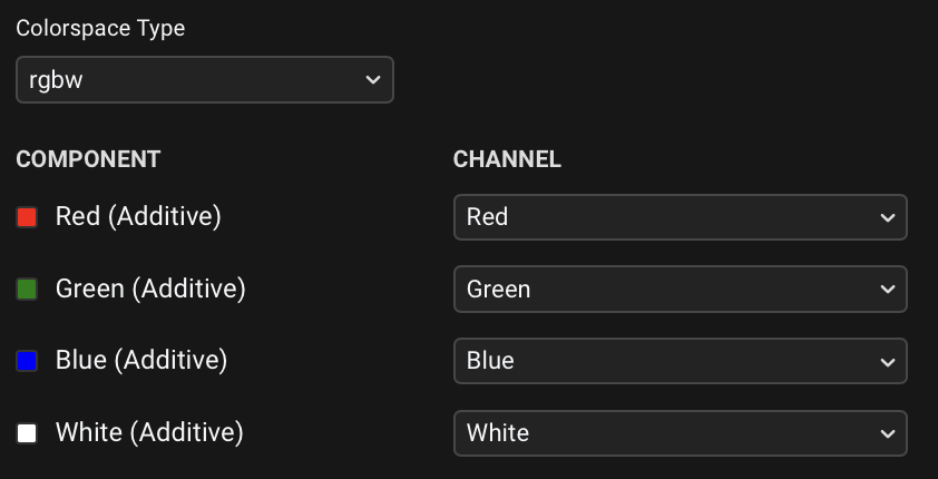
- rgbw
- rgbwi
- cmyi
Choose this if the fixture has no Intensity/Dimmer or color-mixing channels.
Choose this if the fixture has an Intensity/Dimmer channel, but no color-mixing channels.
Once you have chosen the dimmer Colorspace Type, select the Channel that corresponds to the Intensity component:
Choose this if the fixture has Red, Green and Blue channels, but no Intensity/Dimmer channel.
Once you have chosen the rgb Colorspace Type, select the Channels that correspond to the components at the left:
Choose this if the fixture has Red, Green, Blue and Intensity/Dimmer channels.
Once you have chosen the rgbi Colorspace Type, select the Channels that correspond to the components at the left:
Choose this if the fixture has Red, Green, Blue and White channels, but no Intensity/Dimmer channel.
Once you have chosen the rgbw Colorspace Type, select the Channels that correspond to the components at the left:
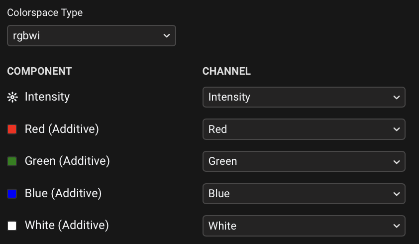
Choose this if the fixture has Red, Green, Blue, White and Intensity/Dimmer channels.
Once you have chosen the rgbwi Colorspace Type, select the Channels that correspond to the components at the left:
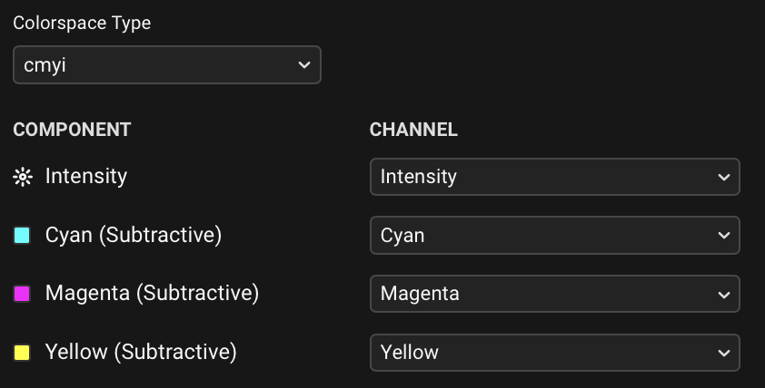
Choose this if the fixture has Cyan, Magenta, Yellow and Intensity/Dimmer channels.
Once you have chosen the cmyi Colorspace Type, select the Channels that correspond to the components at the left:
Unsupported color channels
Your fixture might have color-related channels that are not covered by any of the Colorspace Types, such as Amber, UV or Color Wheel. These should be mapped separately as generic Modulations.
Fixtures with cells
If your fixture has multiple independently controllable sections (cells) - such as a pixel bar with multiple LEDs or a dimmer pack with multiple channels - you'll see multiple similar channels in your list (e.g., Intensity 1, Intensity 2, Intensity 3, etc.). When setting up the Intensity & Color mapping for the fixture base:
- Only map channels that affect the entire fixture (like a Master Intensity channel)
- Do not map the individual cell channels here
The individual cell channels should be mapped later in the Intensity & Color of dedicated Cell sections of the fixture profile, which we'll cover in a later section.
Modulations
Modulations are direct one-to-one mappings between Beam control parameters and specific fixture Channels of any type. Unlike Intensity & Color mappings (which handle multiple related channels as a unified system), each Modulation connects a single control parameter keyword to a single fixture channel.
Using consistent parameter keywords to refer to common channels (like pan, tilt, stroberate, zoom) in every fixture profile, as well as in Beam for Live devices or Beam for Max objects, means you can use the same set of controls across different fixtures, even when their DMX channel layouts differ. Beam translates values of these parameters to DMX values for the appropriate channels of relevant fixtures.
Adding Modulations
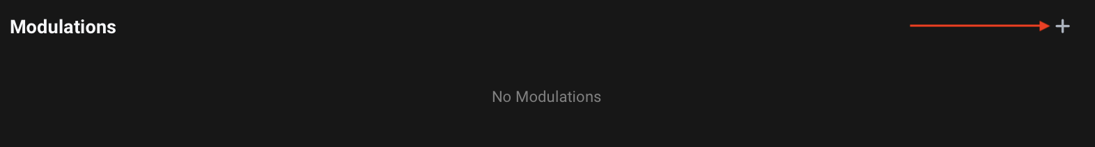
Add a Modulation by clicking the + button at the top-right of the Modulations section:
Setting Modulation properties
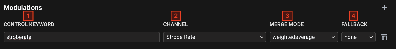
Each modulation entry/row has 4 properties:
- Control Keyword - The parameter that will be used to refer to the channel in Beam for Live devices and Beam for Max objects. Use lowercase and no spaces.
- Channel - Select the Channel that the Modulation will control.
- Merge Mode - Determines how parameters from multiple lighting signal sources (Beam for Live devices or Beam for Max objects) controlling the same Modulation for a given fixture are combined into a single DMX value:
addition: The parameter values of all sources are added together. Useful for combining intensity-like parameters, where you simply want a higher value if multiple sources are using it.weightedaverage: The values are multiplied by the fixture's intensity, added together, and divided by the number of signals. Most suitable for parameters controlling channels with continuous proportional control (e.g.pan,tilt,zoom,stroberate), where averaging results in a more natural mix between control sources and prevents values from exceeding usable ranges.htp: Highest Takes Precedence - the highest value is used. Useful for slot-based parameters such ascolorwheel,shutterstrobeandprogram, where only one value should be active at a time. This ensures that when multiple sources try to control a wheel position or program selection, the one with the highest activation value "wins", rather than creating meaningless in-between values.
- Fallback - Determines what happens if control signals containing this Modulation stop being present in the output:
none: The Channel will go to its Default Value. Relevant for most parameters.last: The Channel will keep its last value. Relevant for parameters likepanandtiltthat should stay in their current position when the signal is no longer present.
Cells
Cells are independently controllable sub-sections of a fixture - essentially "fixtures within a fixture" that you can individually address using Beam for Live devices or Max objects. Examples include individual pixels in LED strips, segments of a lighting bar, and separate light sources within a single fixture.
Adding Cells
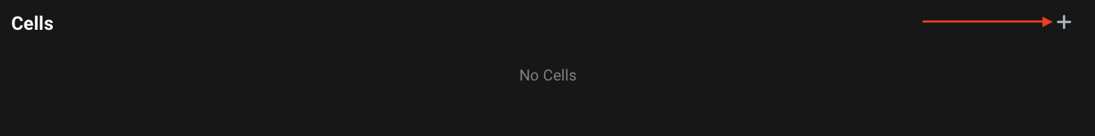
Add a Cell for each section of your fixture by clicking the + button at the top-right of the Cells section.
You can add multiple Cells in one go through the Add Premapped Channels feature, covered in the next article.
Opening Cells and switching between them
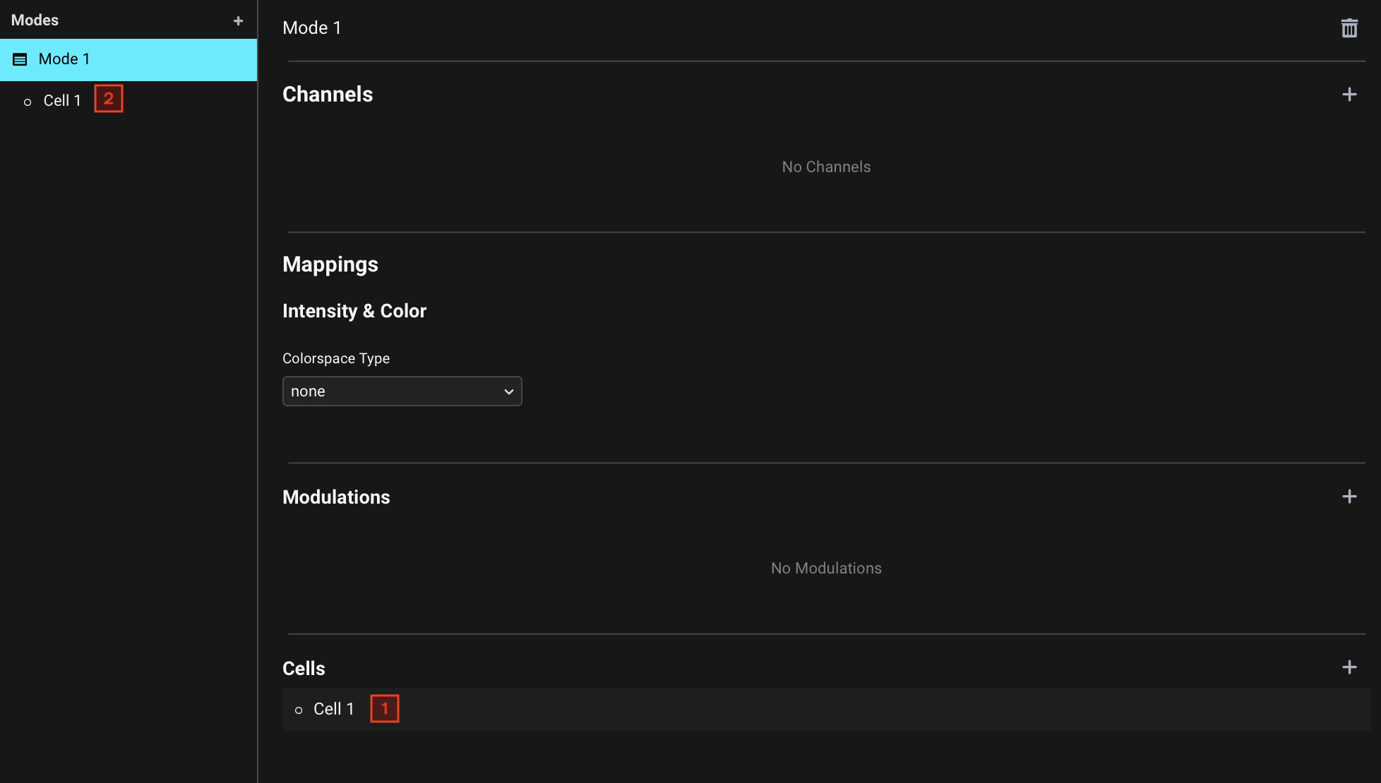
Once you add a Cell, you will see its entry appear both under the Cells list of a Mode (1), as well as under the currently selected Mode on the left-side navigation menu (2).
Clicking on a Cell in either of these two places will set the active view to the corresponding Cell.
Cell Mappings
Just like the fixture base, each Cell has its own Intensity & Color and Modulation Mappings. The functionality of the Mappings in Cells is the same as described in Intensity & Color and Modulations for the fixture base, but you should here assign Mappings based on the available Channels related to the selected Cell.
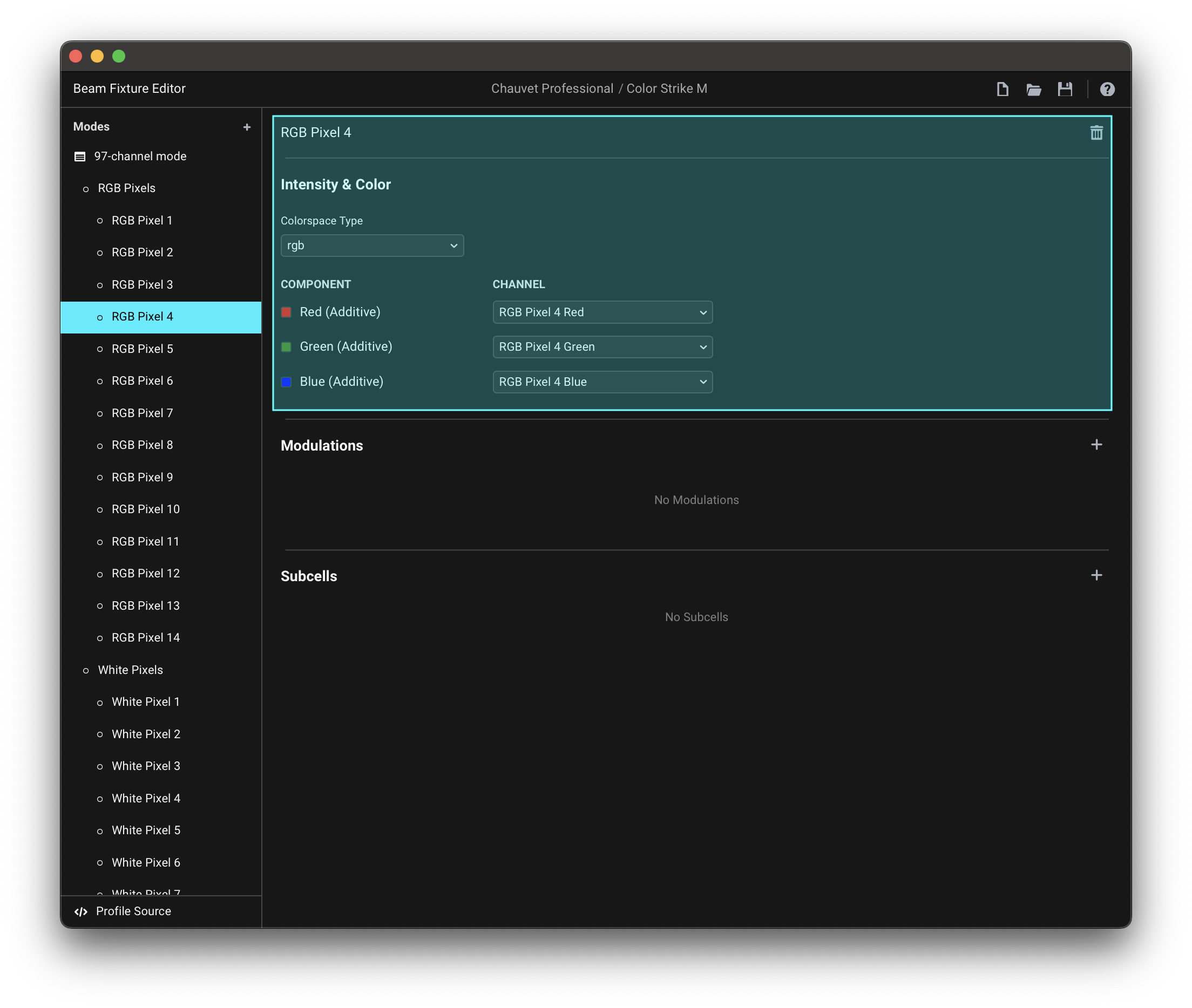
- Example: RGB Pixel Bar, Cell 1's Mappings
If a Cell is the Pixel 1 in an 8-pixel RGB pixel bar, where each pixel also has a dedicated Strobe Rate channel, this is how you would assign Mappings referencing the pixel's Channels:
Subcells
Each Cell can also contain Subcells, which can be added by clicking the + button at the top-right of the Subcells section. This is relevant for fixtures that have several different sections, that each by themselves have individually addressable sub-sections.
- Example: Fixture with multiple Cell sections with Subcells
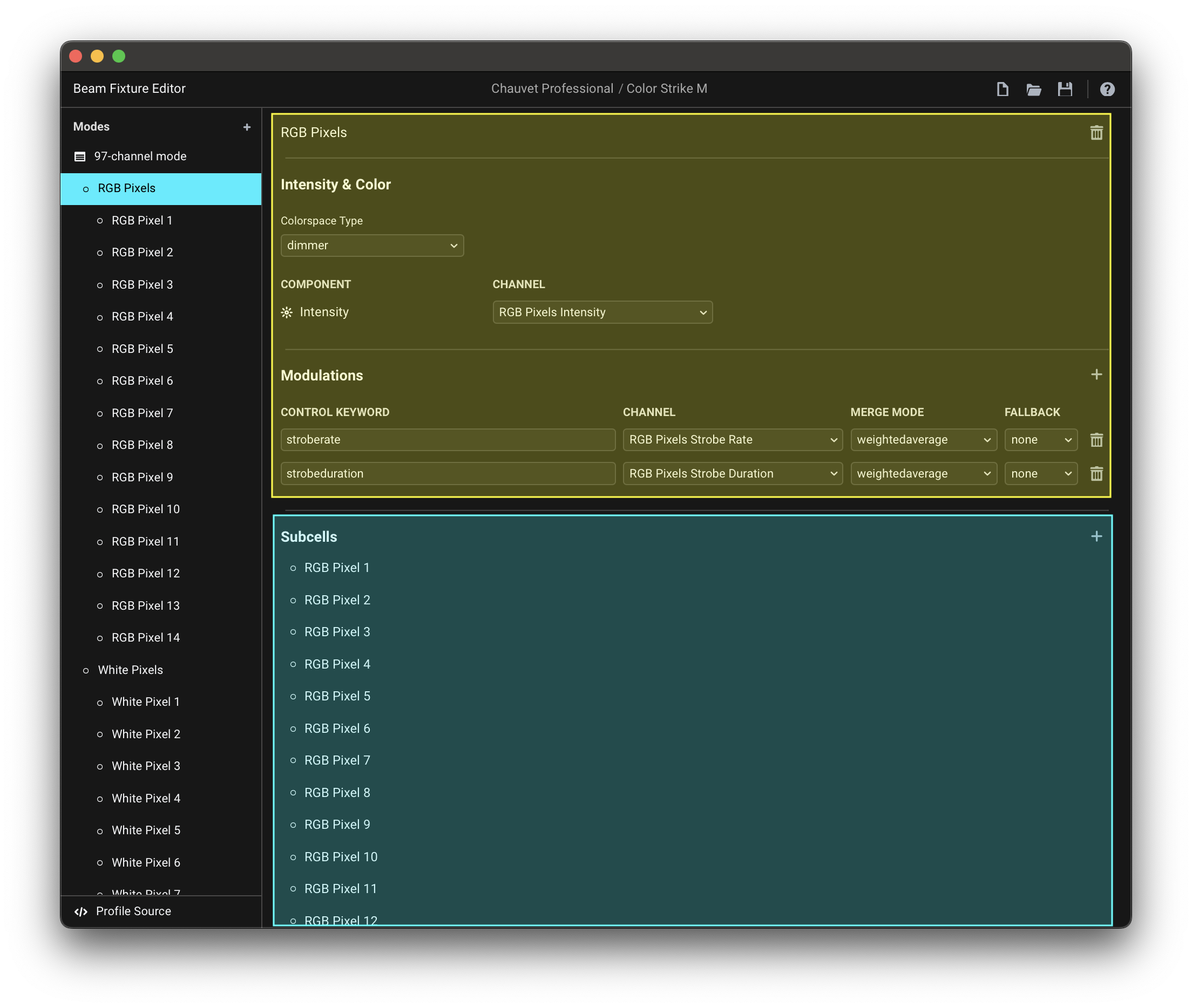
- Cell section Mappings
- Subcell Mappings
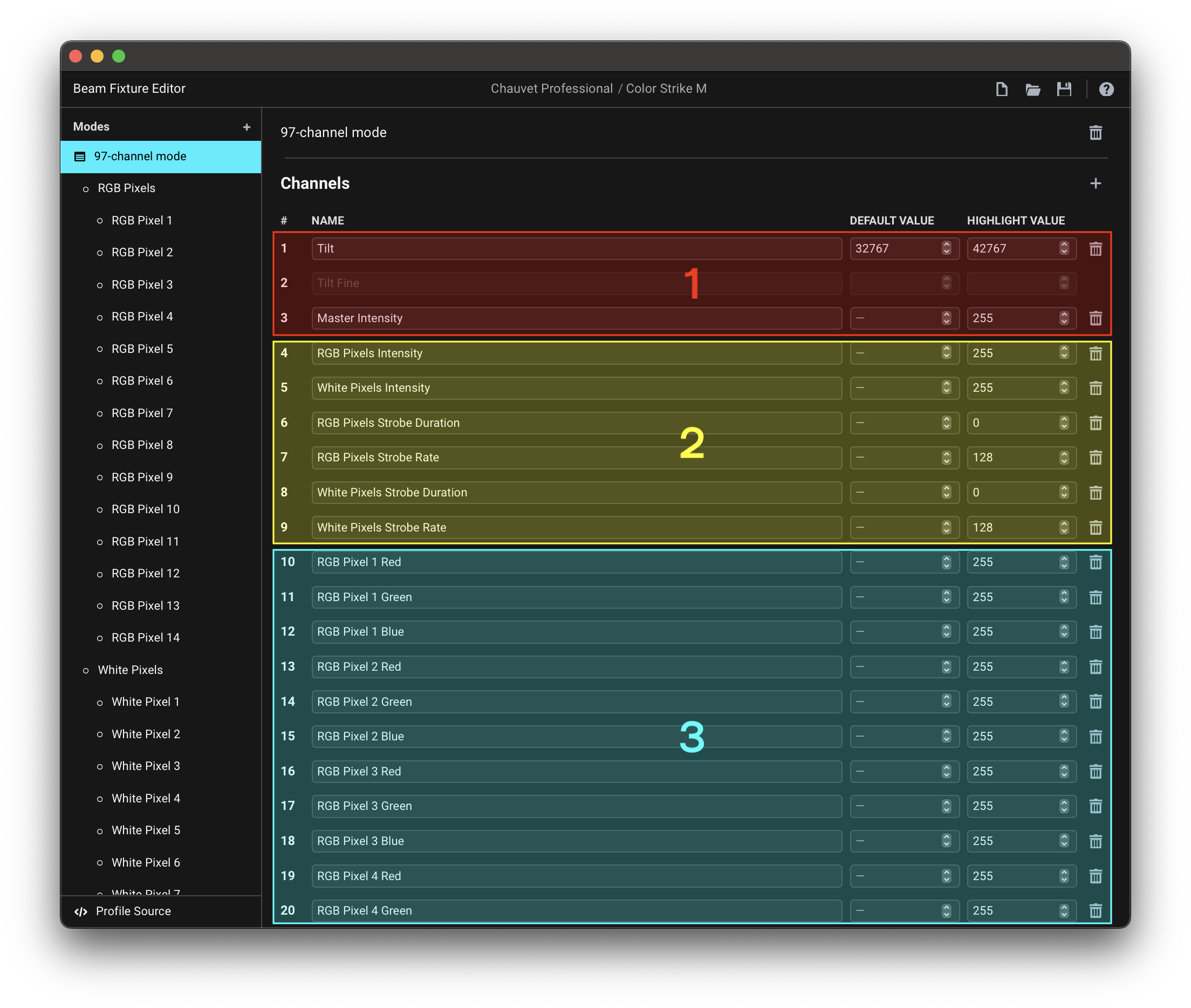
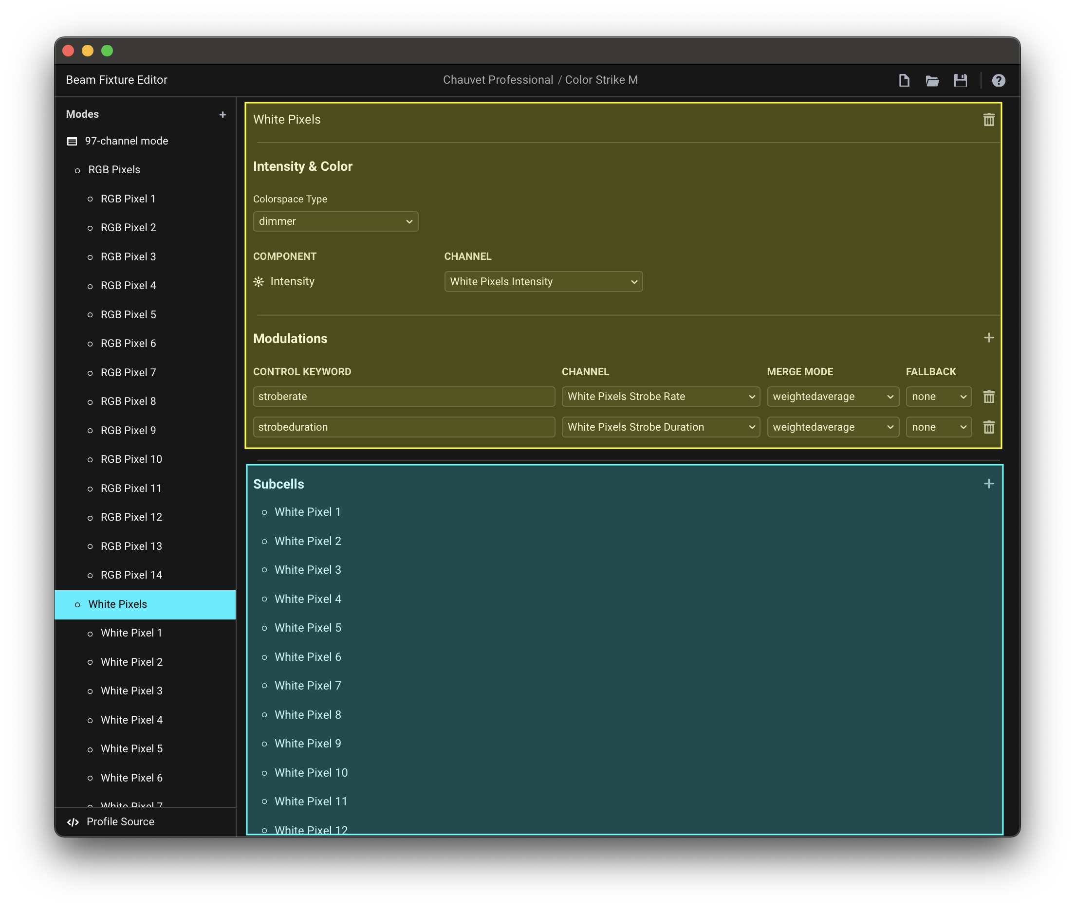
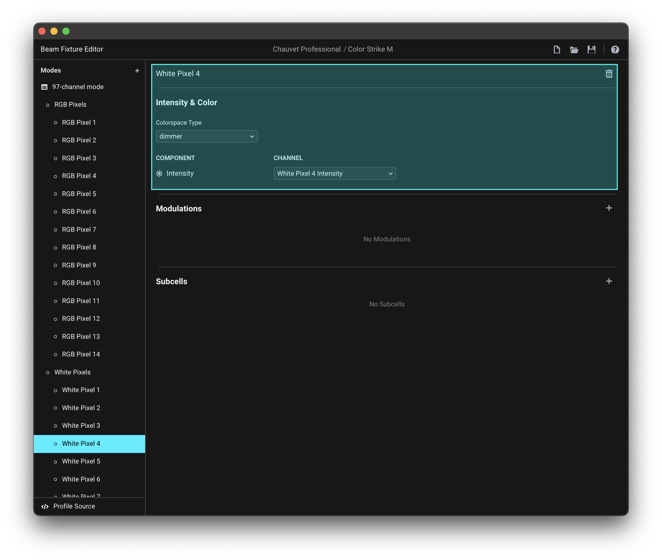
An example of a fixture with Cells containing Subcells would be a tiltable strobe with separate RGB Pixels and White Pixels sections, with channels that relate to the entire fixture (1), channels for each Cell section (2), and channels for each individual Subcell within a Cell section (3):
Renaming Cells
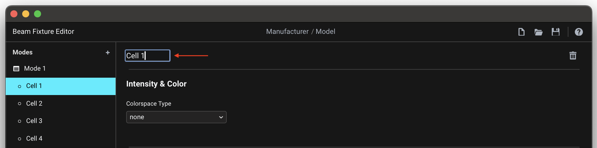
By default Cells are assigned names like Cell 1, Cell 2, Cell 3... You can change the Cell name here:
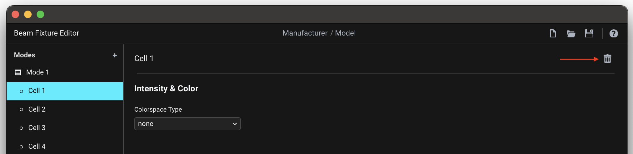
Deleting Cells
To delete a Cell, press the trash-can button at the right of the Cell name:
Conclusion
This covers all the concepts you need to know about in order to create a fixture profile for any fixture. However, the process of making a fixture profile can be considerably simplified and sped up by using the Add Premapped Channels function - learn about it in the next article.